The Recovery Kit Version Two
If you're not familiar with the Recovery Kit, it's something I made back in 2019 and posted to my original back7.co blog. I created it before I knew what a "cyberdeck" was beyond a simple part of William Gibson's Neuromancer. I wanted a rugged computer enclosure for my Raspberry Pi, and I'd been unhappy with overly simplistic and cheap cases for the Raspberry Pi at the time. I had some projects in mind for GPIO, but sadly many of those haven't come to light since I made the Recovery Kit 5 years ago.
I have been making other stuff since then, but the Recovery Kit got picked up by The Verge, the Raspberry Pi Magazine, Hackster, and more- but the bucket list items were from Hackernews, Hackaday, and Uncrate. I'm still a daily reader of all three! In the last 5 years I've lost count of all the variations I've made in CAD to try and make something I felt was an improvement on the well-rounded Recovery Kit. I am grateful for the springboard that the exposure this project has granted me. It's allowed me to connect and share with a pretty special audience. However, my designs over the last few years for an updated RK were left unpublished. They just didn't show enough variation on the original idea. The Quick Kit and its variants have arguably had a bigger impact to people, since it allowed for making a rugged Pi computer with a much simpler assembly process (and without any soldering). The versions I released late last year only need a single 3D printed part and some hardware off Amazon, so making something simpler wasn't my direction here.
Challenges
This is going to be a pretty lengthy post, but if you just want the parts list, it's at the end of the article. For now though, I'd like to talk about some of the challenges with the original Recovery Kit.
The battery. Folks asking for a battery version almost outnumbers the people on Reddit asking, "what do you use it for?". The battery one hit home for me though- the original kit had a battery that could handle the high amperage of a booting Raspberry Pi, but it disappeared off Amazon shortly before I published the post. I was worried that it was a safety issue or recall, so I had to omit it. I'm using a much larger battery this time, and I think I have a good approach for the new builds- more on that in a bit.
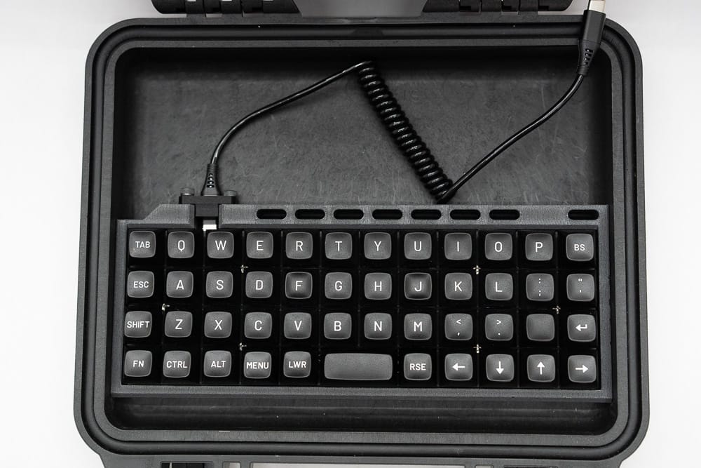
The keyboard. The original keyboard is the ortho style for one major reason beyond looks- ANSI keyboards are just too wide to fit in the lid of a Pelican 1300 case- maybe a 40% might but that's asking too much of people. The height of the lid was a real issue ergonomically too-typing on a keyboard surrounded by a lid's lip like that is not fun. On top of that, the original Plaid keyboard wasn't programmed when it shipped, and the instructions for programming the chip were... not written well. That made it really hard to recommend. I have a newer pre-built keyboard that will lose me points with the handmade crowd, but hopefully this is easier for people to use. Keyboards are still tough though- they don't stay in stock for long.
The original Recovery Kit wiring. Just look at it!
Seriously- I love the look of that harness, but between that and a through-hole keyboard kit, each deck took more than 100 hours to print. That made the deck too hard for most people new to soldering, but also too expensive for most people to buy commissions. I am open for commissions on the new build through the end of June 2024- email me if you're interested!
The handle. That handle and the clevis joints making the ends of the handle just above the monitor would catch on the Pelican case, rotate, and damage the screen. Not good, and the handle is barely usable there. I have a better option this time though.
The GPIO. I actually still love these, but these connectors are also pretty hard to solder. The new one uses crimps. The idea is still the same though- I want an easy way to access GPIO for custom add-on boards and devices.
Compromises
While I think I have good options for the stuff I have covered so far, there are still a few compromises I needed to make this time. Maybe these will be in a larger deck sometime?
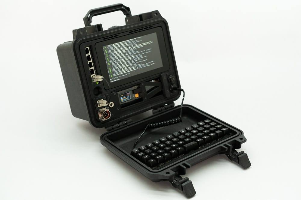
Screen Size. The Raspberry Pi 7" Touchscreen display is laughably bad for a desktop, but pretty decent for a terminal. That's why you see the RKV2's here sporting terminals. You can run a desktop, but why? One good reason is to launch your favorite SDR app. I don't actually intend on using this with a window manager though- this will be the workhorse the original was intended to be, enabling other devices off-grid.
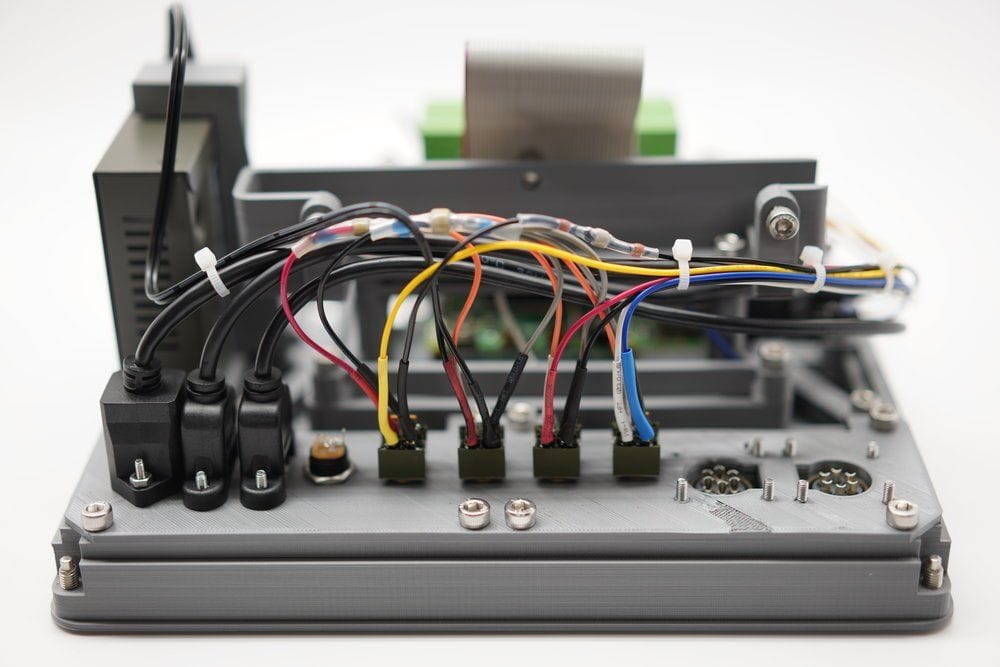
Power controls. With all the changes I made, there's not the room I once had for individual power toggles. This time there's a simple push button for the Raspberry Pi 5's power switch, or a GPIO input for the Raspberry Pi 4. Internally there's simple plug connectors- less glamorous but also easy to mod and use as needed. Again, reducing the amount of solder here as much as I can- and this is the only solder joint! While I am appreciative that we have a couple through-hole connectors, I would have really loved the Pi Foundation to use a connector for this.
No x86. Not yet!
Build Overview
With all the background info covered, let's get into the build. The general concept is still the same, but with modern printers like the Bambu or other more open CoreXY printers, this is a pretty easy parts list to print.
It goes together easy, but with a mix of M4, M3, and M2.5 screws. No more M5 screws this time around, but an electric screwdriver is a must. I ended up using a Hoto and the bits from my iFixit Mako Driver Kit - the tools are also linked at the end of the article.
I also used Bambu's own Carbon Fiber PETG. Either Pelican or Orchestra changed their dye color since the original Recovery Kit, and it wasn't a good match this time.
Network Switch- the same reliable 5 port gigabit switch is here, but has been press-fit into place this time- the accuracy of Fusion 360 and the repeatability of the Bambu X1C has let me really dial in this printer- so no ugly boot on the back holding the switch to the frame.
Ethernet - Of course Ethernet is making an appearance! This time we're using a slightly more expensive passthrough from McMaster Carr, but I'm hoping to skip the drama I ran into with the Quick Kit of parts shortages. If you haven't used McMaster Carr you should check it out- their website is an amazing collection of industrial parts complete with visual references and specs for each part.
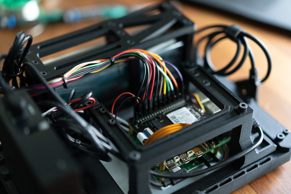
GPIO is back again, but far more condensed this time to make room for the battery. It took some squeezing but there are plenty of GPIO pins to re-use, and I am happy to say the connector is from McMaster Carr, but the crimpers are far cheaper off Amazon, and will be linked at the end of the article. With crimpers on some extra long silicone jumper wires, they are easy to move around- I will probably add labels though, since I don't quite have the variety of cable colors that I did last time.
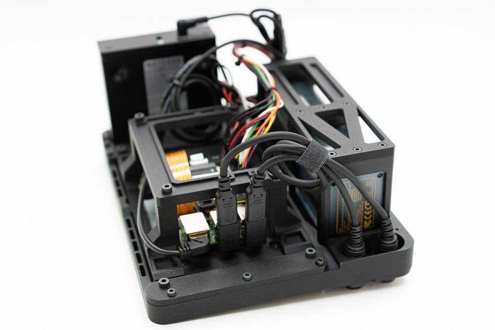
USB-C connectors are all over this build, and it could be cleaner- but with a few zip ties or fabric cable ties, this build actually comes apart pretty easy. There's a couple key things to keep in mind:
- The USB-C power on the Power Bank is "smart" and will not see the Pi or network switch when the battery is first turned on, so you have to unplug and re-plug the USB-C connector on the battery. A custom circuit may be better in the future, but considering we're using off the shelf parts, this is a compromise I had to make.
- There are two USB-C ports that map back to the USB ports on the Pi. You can easily "hotwire" one of them with a USB-C female-to-female adapter and make one a power port for the whole system. There's a ton of options here, and it turned out to be really helpful building this system.
- My setup uses right angle USB-A to USB-C connectors, and those might block the other ports- if you need all four Pi USB ports, you may need a few more adapters.
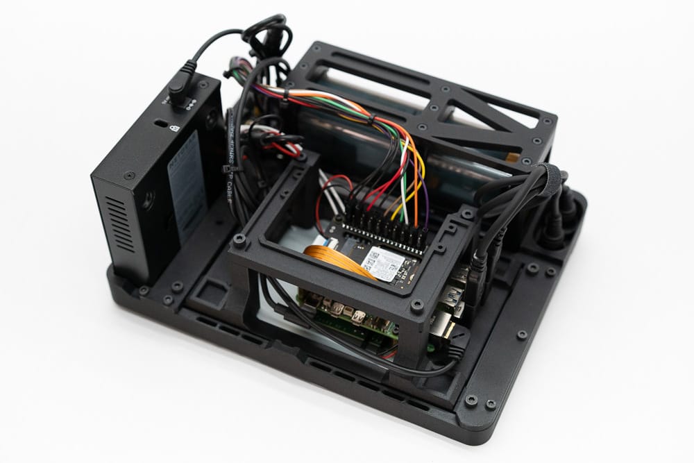
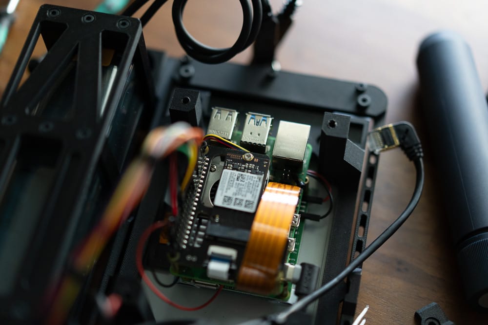
Now for the good stuff- the NVME and the battery! This system is able to run a full NVME drive as the boot drive AND do it all from battery. I intentionally have space around the battery and vents at the top of the enclosure, but the system runs great at normal room temps. With a black enclosure I don't recommend leaving this in the sun. Jeff Geerling has a great writeup including the commands needed to boot from the NVME.
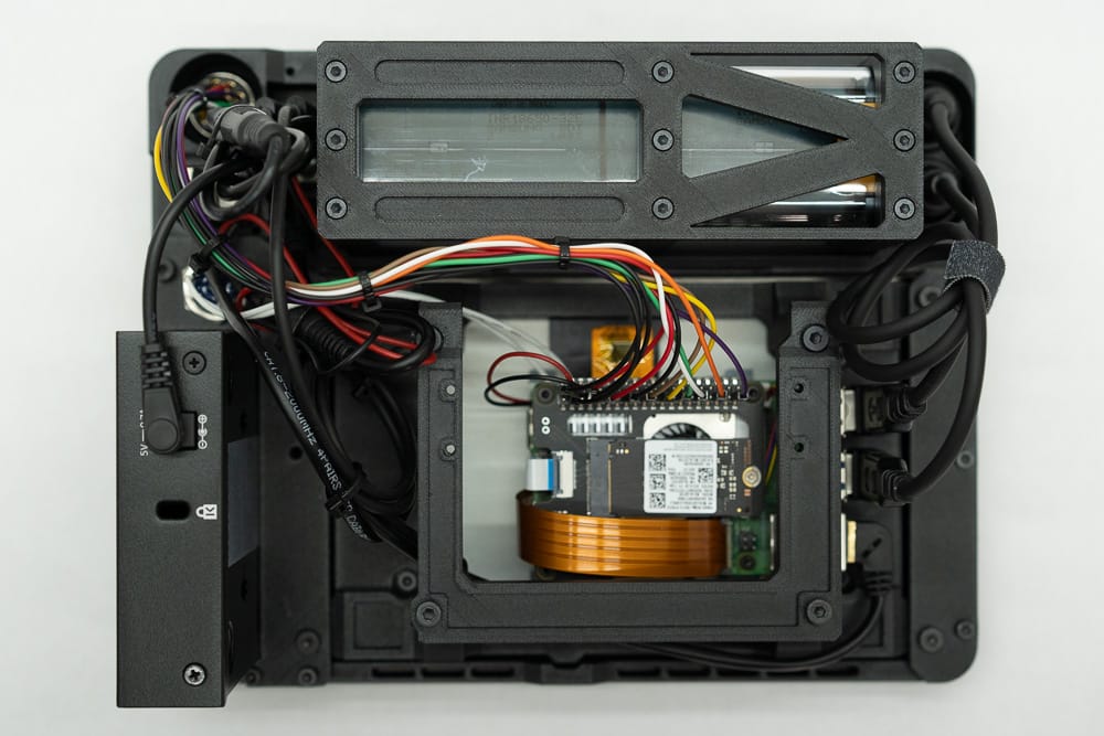
The DSI cable (in copper above).
This DSI cable has got to be one of the things I like least about the direction the Pi Foundation has gone. Simply put, the new connector for the CSI (camera)/ DSI (display) ports is smaller, requiring a new cable. Here's the catch though- it's physically the same size as a million of them on Amazon and Ali Express, but the only one I found to work was purchased from the Pi website/vendors... and there's a specific cable just for the displays, and another specific cable for the cameras. This is not something that's easy to find at the time I write this.
The Power Button. This is one of my favorites, it really adds a nice touch and helps for a quick shutdown, but really you can rewire it to GPIO if you want, especially if you plan to use a Pi4 since only the Pi5 has the solder points for the button. In a pinch you could also print your own part and use this as a radio connector too if you're doing an internal SDR. There are mounting posts and a frame for mounting an internal SDR if you want, but for now on this build it's a humble power button with a nice click to it.
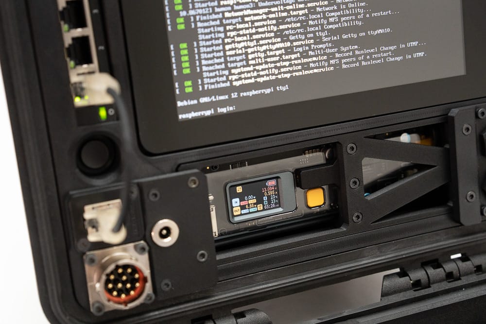
Let's talk about the battery. I am using the Shargeek Storm 2 100W, 25,600mAh power bank. Aside from doing the normal autosense that all smart banks do, this one has really held up well! Even with the NVME it boots up fine and runs great- some builds of Raspberry Pi OS complained breifly about undervoltage, but I think that's an artifact of how the Pi5 tests- the screen showed that the Pi5 never came close to the battery's limits. If you're going to keep this in log term storage, unplug the USB connector from the battery, or remove it altogether- the whole frame comes out with just a few screws.
The big downer is that we can't charge and use this battery at the same time- so that "hotwiring" of a USB-C port really helps here.
the Keyboard is our last stop before covering the parts list. It's a Drop/OLKB Planck v7. This is a kit available as no-solder and I am using the white-on-black keys here. While you can use the stock case, I made one a little bit wider that can wedge into the lid. This leaves it tucked away for convenience and travel, but can pop out on a desk for daily usage.
The Recovery Kit Version Two took quite some time, and I'd like to thank my subscribers for supporting me with this build. Paid members will have access to the post on my site that contains the STL files for this build, and the CAD members will have access to the Fusion 360 design files. Monthly membership with access to the STL files for all my builds starts at just $5 a month, but the annual membership is heavily discounted and really helps me out. Thanks for reading, and thanks for your support!
Parts List
Core Compute & Display
Raspberry Pi 5 - Amazon, Adafruit, Sparkfun, Digikey (Amazon may be faster but is almost always a scalper or reseller, so beware).
Raspberry Pi 5 Heatsink - Amazon
Pi5-Specific DSI Cable - Sparkfun (DO NOT USE THE GENERIC VERSIONS OF THIS CABLE)
Pi5 NVME adapter - Amazon
2242/42mm NVME - Amazon
Raspberry Pi 7" Touchscreen Display - Amazon
Ethernet Switch - Amazon
Cables & Adapters
Right Angle Ethernet Cable - Amazon
Zip Ties - Amazon
Hook and Loop Ties - Amazon
USB-C Cable (for the Pi) - Amazon
USB-C to Barrel Jack (for the network switch) - Amazon
Right Angle Barrel Jack (for the network switch) - Amazon
Short Ethernet Patch Cable - Amazon
30cm Jumper Wires - Amazon
Right Angle USB A Male to USB-C Female (2x kits): Amazon
Front Panel Connectors
DC Power jack - Amazon
GPIO Connector (Panel mount male) - McMaster-Carr
GPIO Connector (Female connector for any cable/IO you want to add) - McMaster-Carr
Panel Mount Ethernet - McMaster-Carr
Power Button - McMaster-Carr
Quick-Connect wires for the Power Button - Adafruit
Panel Mount USB-C (x2) - Amazon
Battery
Shargeek Storm 2 Battery - Amazon
Right Angle USB-C to 2x USB-C - Amazon
Keyboard Components
OLKB/Drop.com Planck v7 PCB - Drop.com
Keycaps (MT3 White on Black) - Drop.com
OLKB Switch Plate - Drop.com
Coiled USB-C Cord - Amazon
Cherry MX Switches - (3x) Amazon
Screws, Case, & Misc Hardware
Pelican 1300 Case - Amazon
M4x10mm Socket Head, Black Oxide - McMaster-Carr
M3x10mm Socket Head, Black Oxide - McMaster-Carr
M3x20mm Socket Head, Black Oxide - McMaster-Carr
M3x8mm Flathead, Black Oxide - McMaster-Carr
(All these screws can be ordered from Amazon as well, but the McMaster-Carr tend to be much higher quality, and in lots of 100 or 50, so you have some for the next project!
Tools
HOTO Electric Screwdriver - Amazon
iFixit Mako - Amazon
Connector Crimpers (required for the GPIO connector) - Amazon
Pinecil Soldering Iron - Amazon
Digital Files
Digital files are for paid members only- signing up is very reasonable with membership granting you access to all my designs. CAD and Elite members can access the CAD and STL files here, STL members can access the STL zip file via this post.
Comments ()