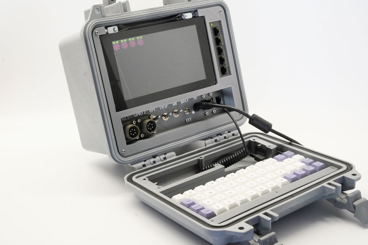
the Raspberry Pi Recovery Kit
Building Internet-connected things seems obvious today, but what about when there’s no Internet?
The concept often feels like something out of a science fiction movie or a doomsday prepper’s handbook- and while this device can work in both scenarios, it’s also about understanding resiliency for your projects and being a good steward of the systems in place today.
I’ve been posting the progress of this project on Instagram, Twitter, and Facebook all month, and this is my full build log of the project. You’ll find the parts list at the bottom of this article. They are affiliate links that help me make more cool stuff, and by using them you don’t pay any more than usual- so thank you for supporting my projects, even just a little bit.
I posted about a month ago on my retrospective from four years ago when I made the Raspberry Pi Field Unit, which was generously shared on Hackaday then, and I posted a follow-up on Reddit several weeks back. There’s a few common issues that I came across:
- There was no keyboard!
- The solution isn’t truly waterproof
- Numerous holes in the case would make ingress of water or moisture even more common
- My wiring on the original project was a mess
- The display took up too much room and was too hard to mount
- The project was too hard to maintain or fix
- Several connectors were very fragile
- Material choices for the internal structure were not good- I picked plastics that were too brittle, and the overall structure was poor
- No EM shielding from the preppers in the audience
I could go on and on, but those are the key points. I’ll address each of these below:
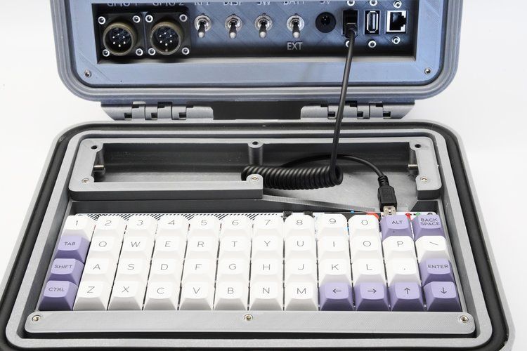
No keyboard
In 2014 I wasn’t aware of any reduced footprint keyboards, and I did look. Even looking today there wasn’t any that fit common search terms, but as a lurker in /r/mechanicalkeyboards I did find out and had already bought a Plaid keyboard kit. As luck turns out, it was a perfect fit. It’s my first ortholinear keyboard, but it matches the cyberdeck feel of the project. I’m using DSA Beyond keycaps and Cherry MX Silent switches, all hand-soldered.
Waterproofing Issues
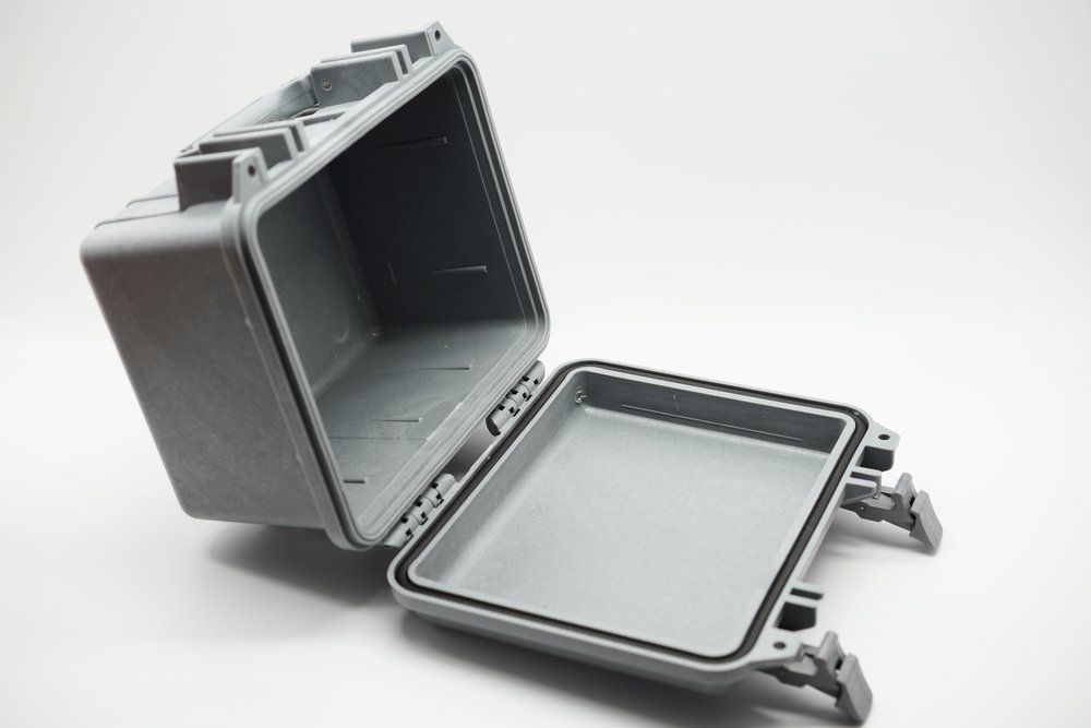
To state it up front, I did not intend to make something fully submersible for long periods. This is a hobby project and in order to do that, you end up using high-end adhesives. No thanks. Instead, I chose to move all the components and connectors inside the Pelican case. While not all Pelican cases seem to be rated to be waterproof, I’m at least not drilling any holes into this one.
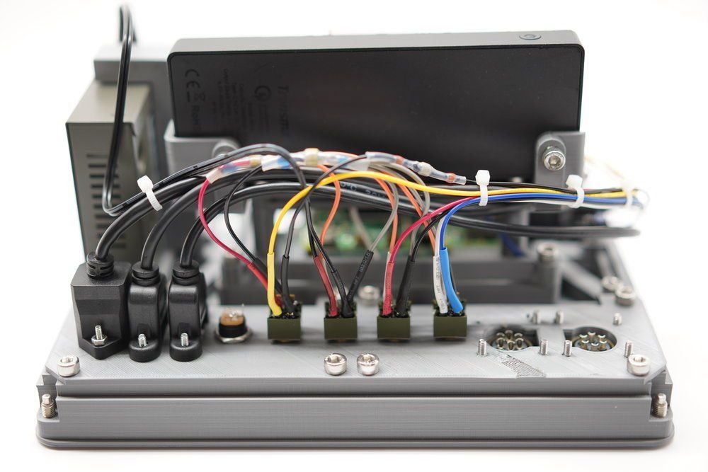
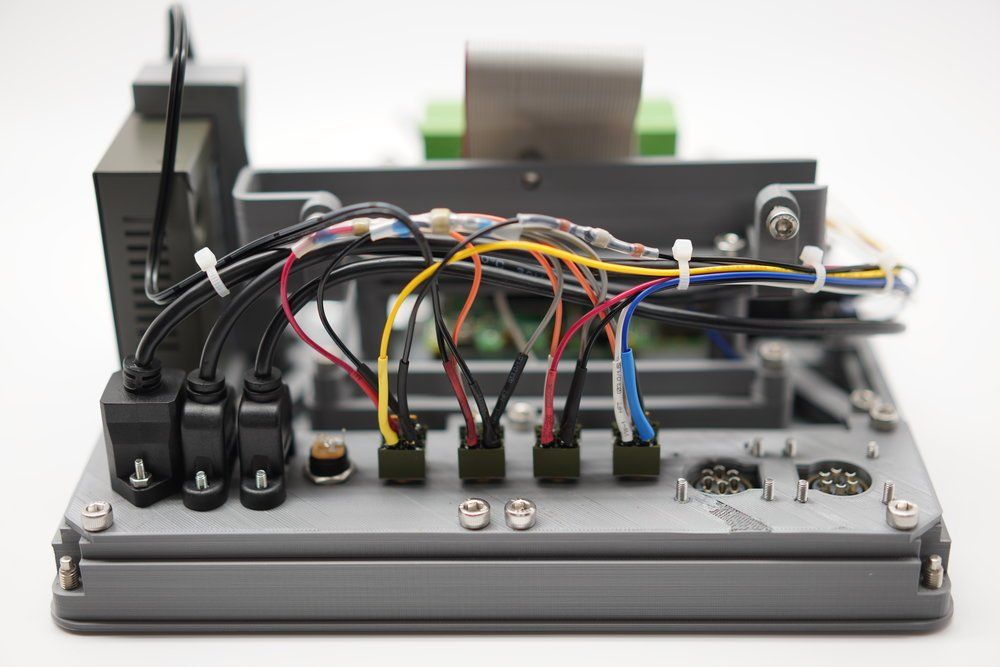
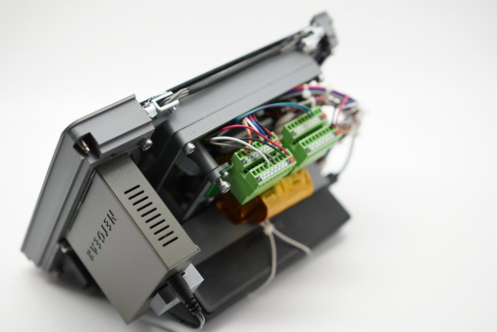
Wiring
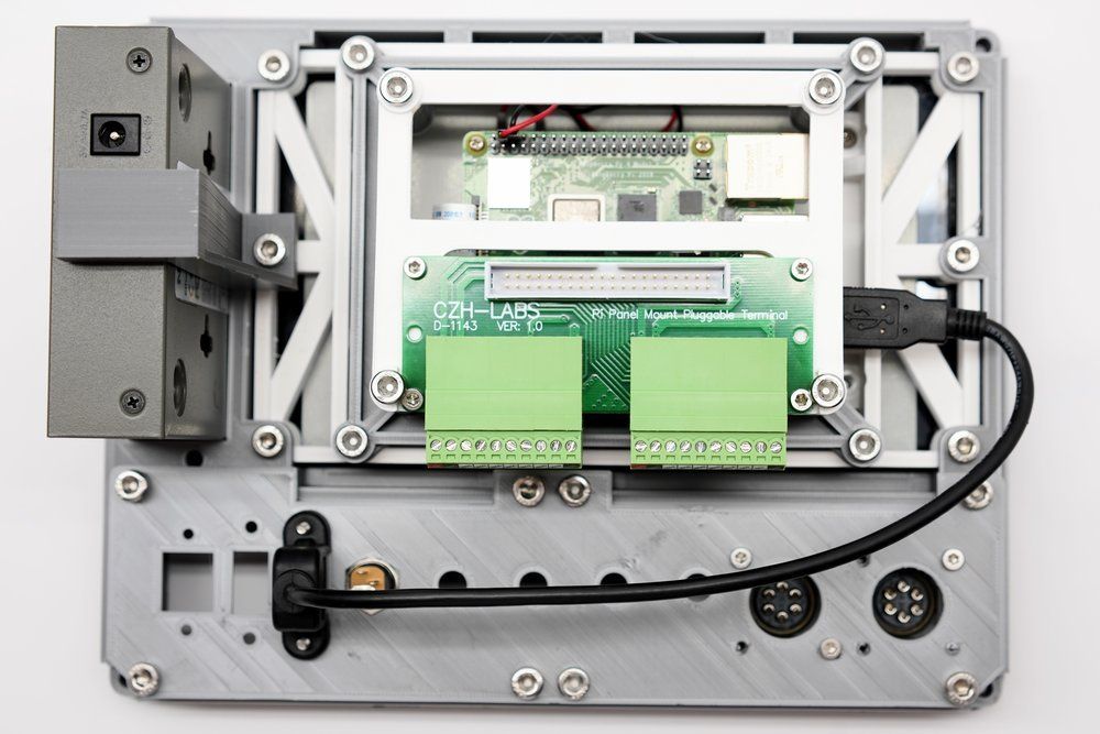
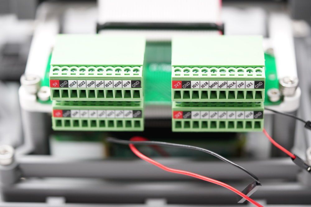
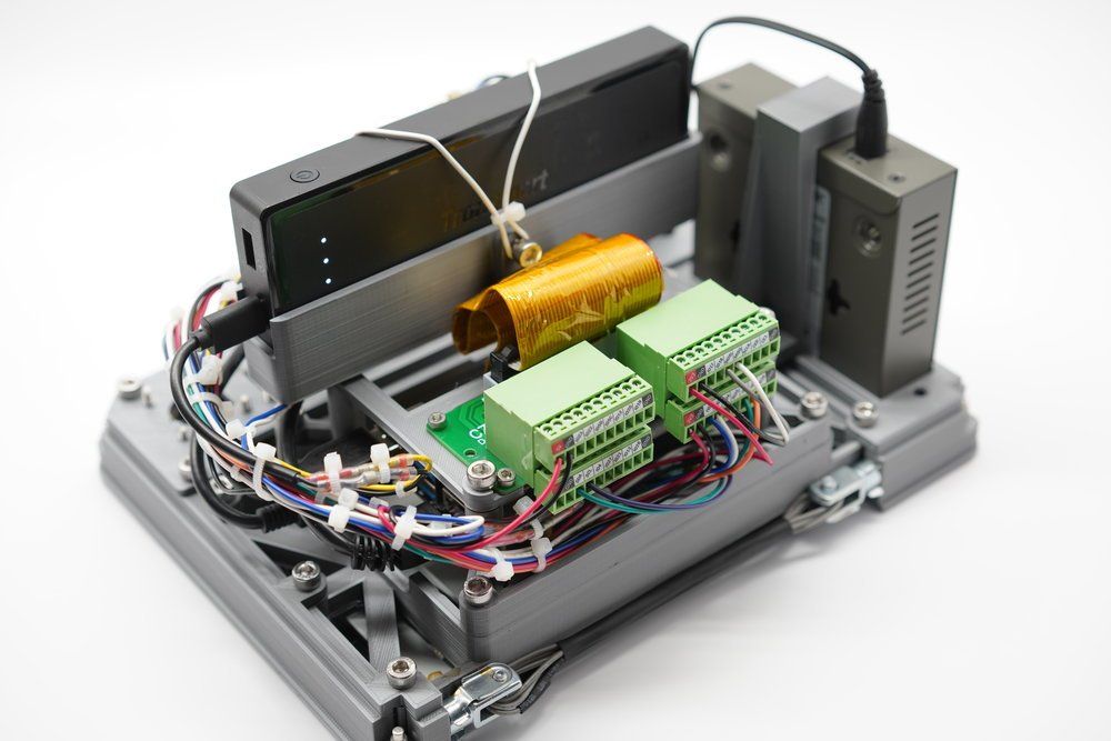
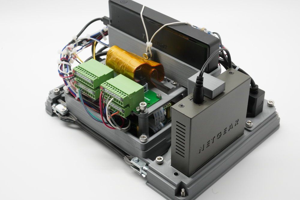
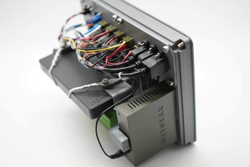
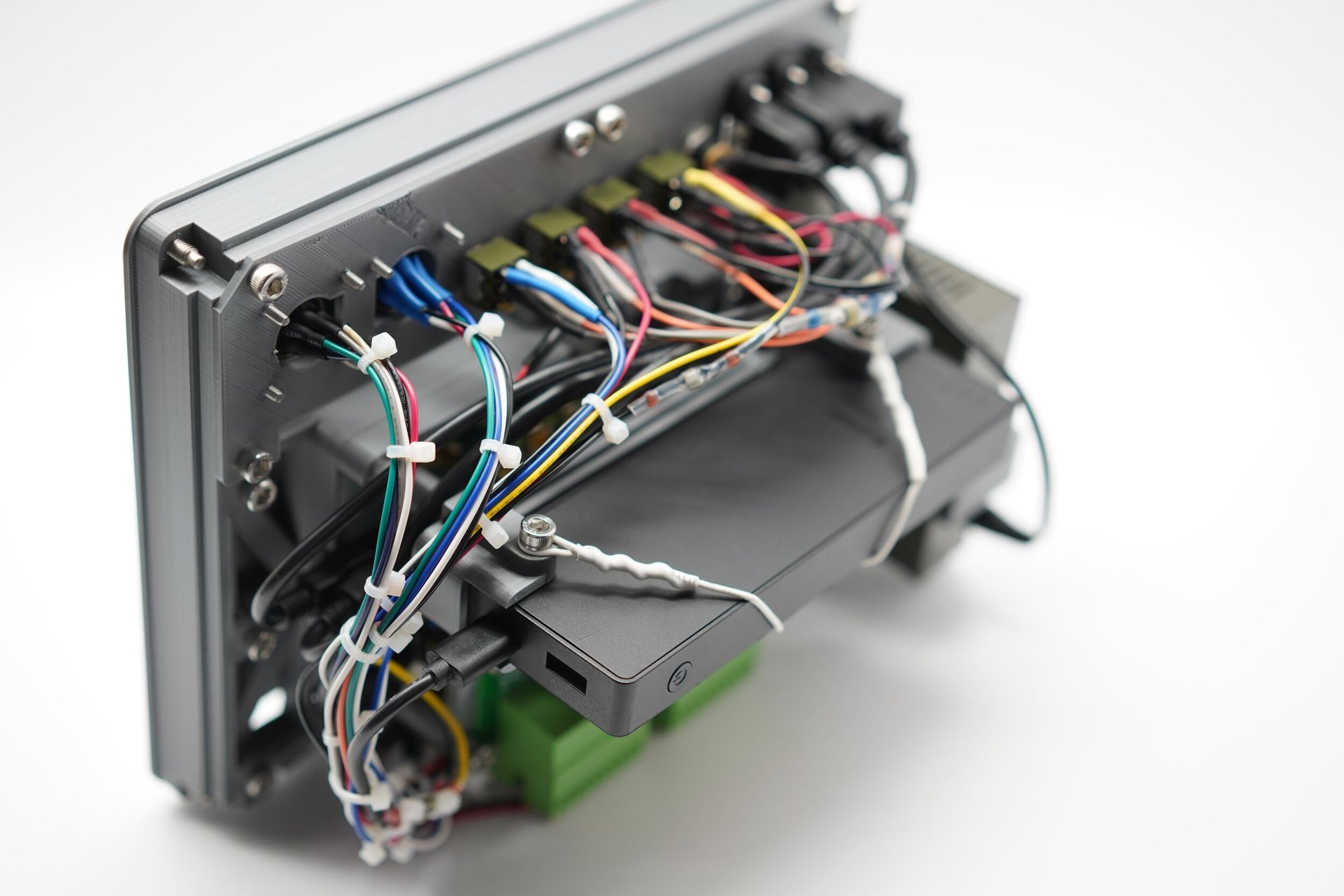
My wiring abilities from several years ago were pretty poor- notably I just randomly selected lengths of wire and shoved in what didn’t fit. Two simple rules seem to have helped me wire this project better. First, use only the length of wire needed, but make sure there’s slack to do connecting and soldering, and make sure wires are equal length when connecting to the same part. All of those more or less go together, but help reduce the amount of clutter. Second, I try to zip tie cables that route together. Zip ties can be the enemy, but in small confined spaces they’re very important. By grouping cables logically, it’s easier to trace cables when troubleshooting. On this project I also grouped the smaller groups together, since I had to route around some of the internals. All in all, I’m really happy how it came out.
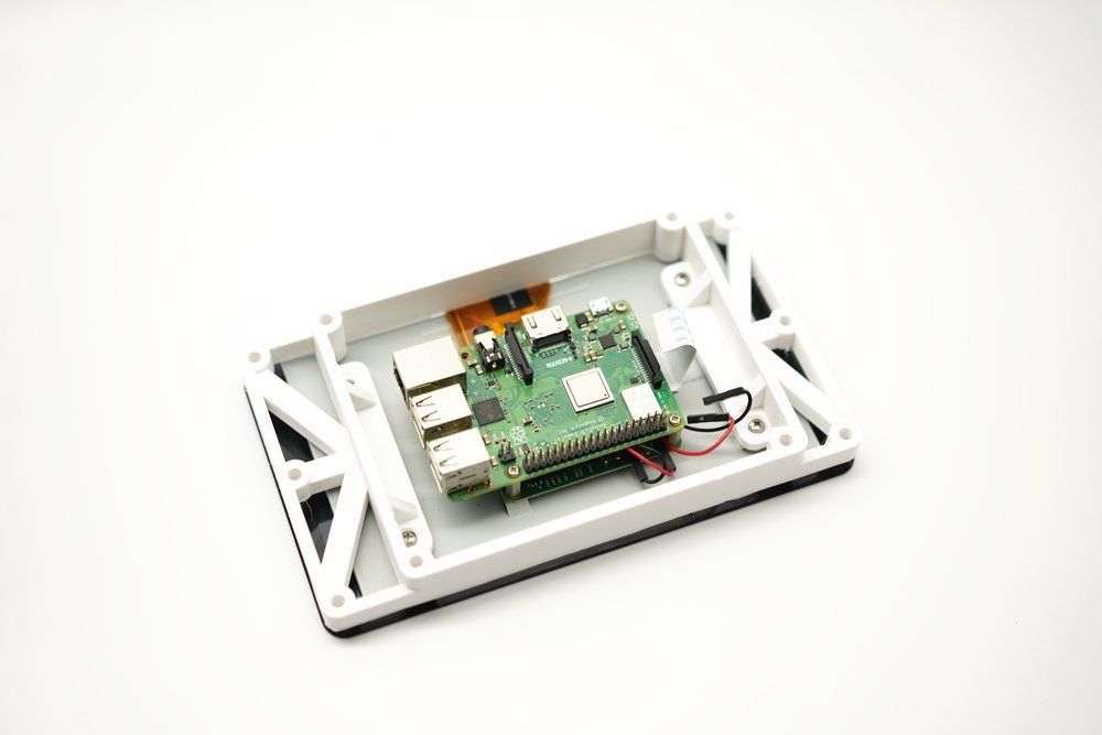
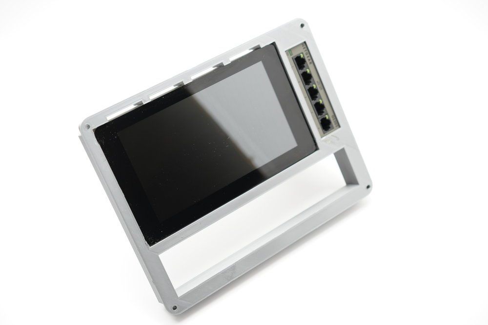
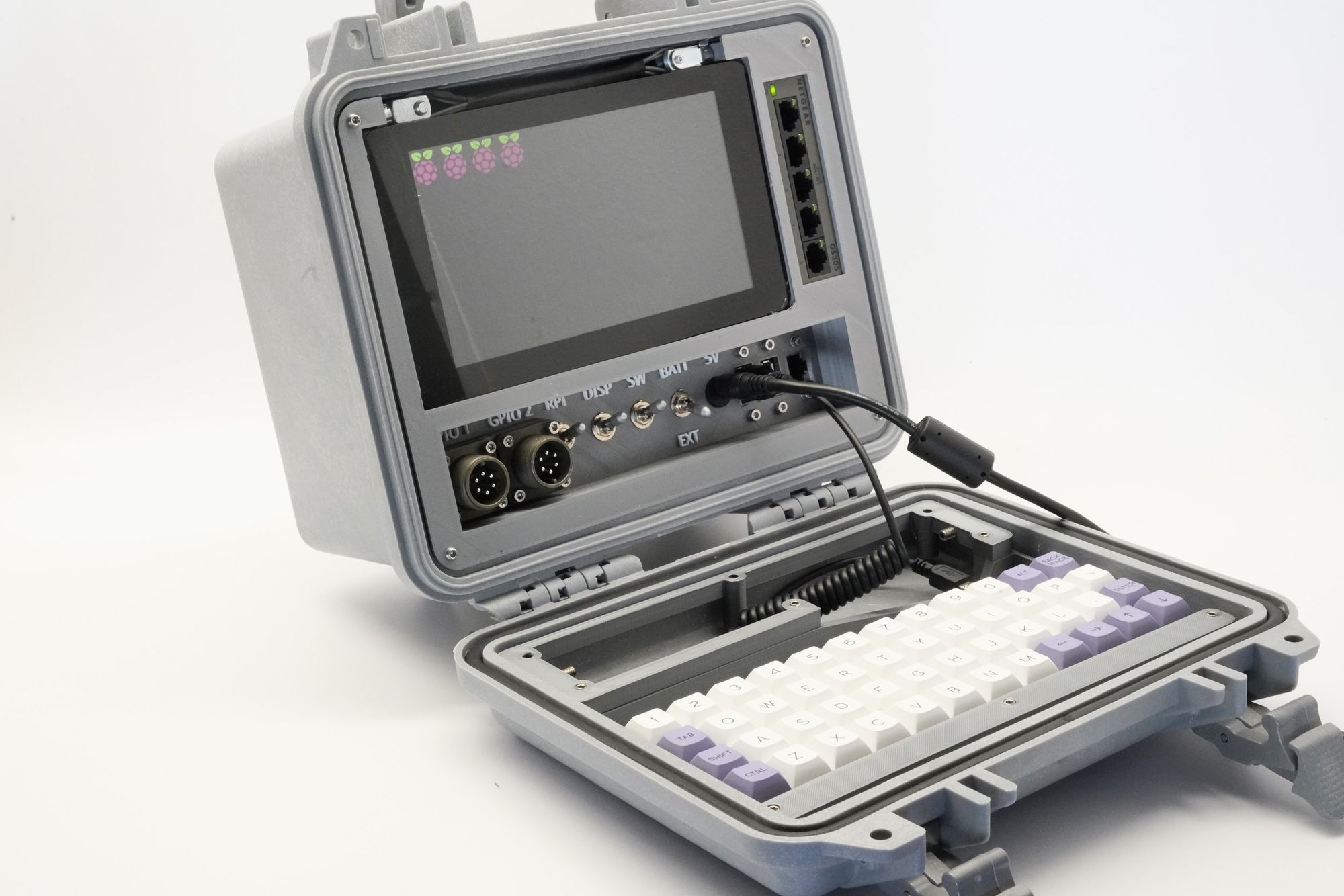
The display on the old project is front and center, mostly because that was all that would fit. This led to compromises on internal design and connector placement. This time I used a smaller display, a 7” Official Raspberry Pi display. There’s a few benefits to this display- it has great mounting hardware and it’s also a touchscreen. That really makes it easier to skip using a mouse, which would have used a USB port- and those are in short supply on a build like this. The display also runs off 5V, so I didn’t need any of the 12V circuitry like I did on the last build. Reducing component costs is something I try to keep an eye on, and by reducing component count, I reduced wiring and the space the power circuitry used.
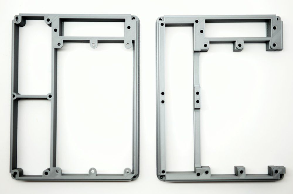
With all I’ve gone over so far, it should be obvious the original version was very complex- I still have it and love it, but it’s nearly impossible to maintain. The wiring is a mess, and some of the components are discontinued. This means maintaining it is something I’ve just plain avoided. I mentioned poor material choices, and that included using a thin plastic sheet. Even though it was precision cut over at Big Blue Saw all these years ago, I didn’t leave enough tolerance from the edges, and I picked a material that was too brittle. If I had to go back again, I’d probably use sheet aluminum and cover it with vinyl- that alone would get me quite a bit of space.
Instead, this time I printed all of the internal parts on a 3D printer, namely a Prusa I3 MK3/S. That gave me the ability to iterate quickly and test more risky designs, but it also meant that some parts like the main frame I printed 3 or 4 times, and each took more than 24 hours to print.
Connectors
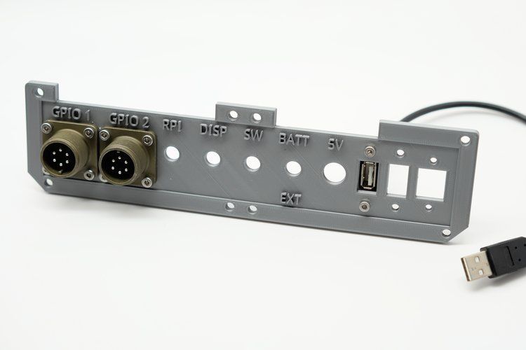
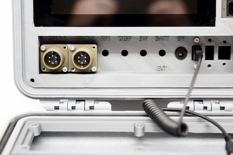
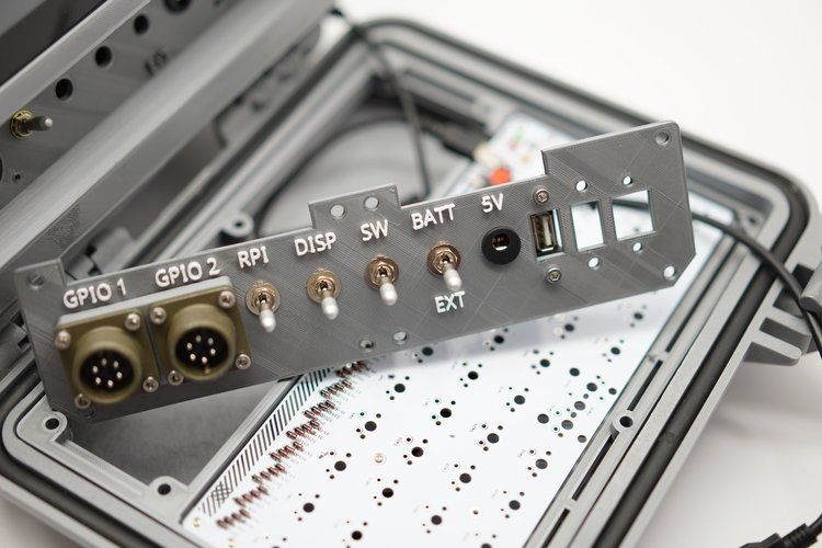
This time I still used two mil-spec connectors from McMaster Carr, despite their price. I already had them on hand from another project, and their panel mounting options are really solid. As you can see in the photo below I crammed as many connectors is as I could.
I also had to offset some of the connectors or switches based on their depth to make sure they were still usable while still being able to close the lid. This time the connectors are very functional, the mil-spec ones can be easily remapped to whatever Pi pins you want with a simple flat head screwdriver.
Most of the other connectors I used this time are pretty affordable, coming from either Adafruit or Amazon. I really wanted to add a USB C connector, but the panel mount options for USB C were simply too big to make sense on the panel.
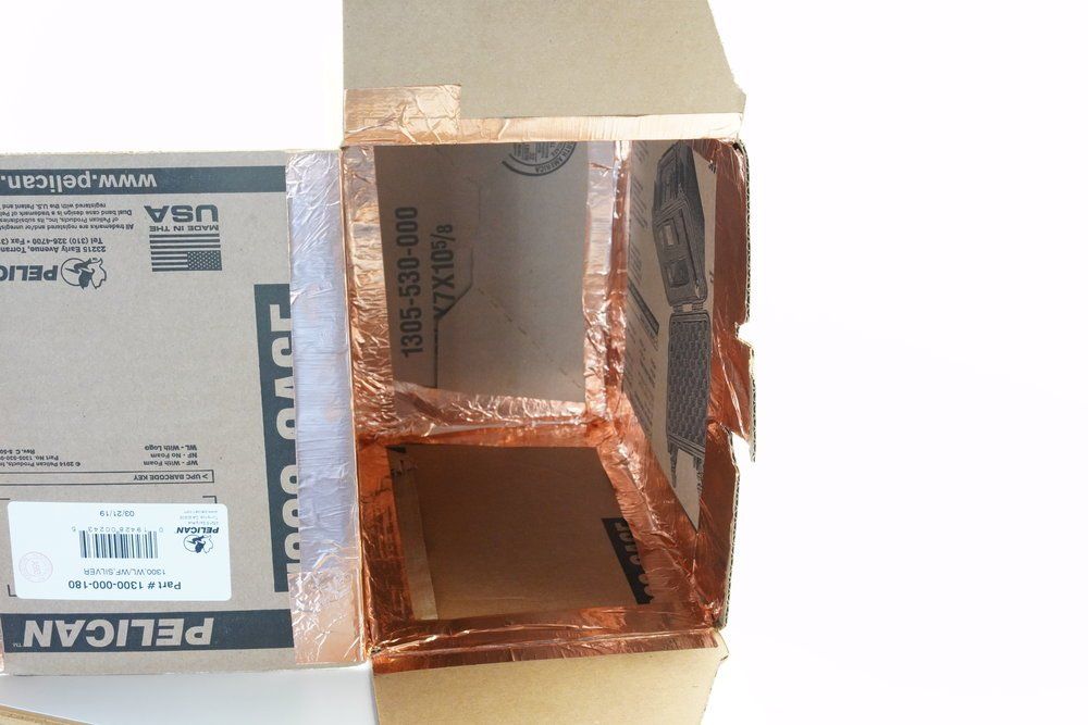
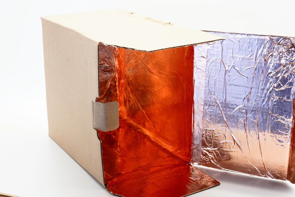
EMP Shielding
Electromagnetic pulse shielding is something spent quite a bit of time thinking about. I could have lined the inside with copper, but any EMP shielding would also block WiFi signals. There’s no great option for external antennas on the Raspberry Pi, so it was either have WiFi or EMP shielding in the case.
I ended up making a compromise and shielded the box that I store the project in. You can see the gallery below of how I cut the box at the seams, turned it inside out and re-glued it, then lined it with copper foil and distressed the box.
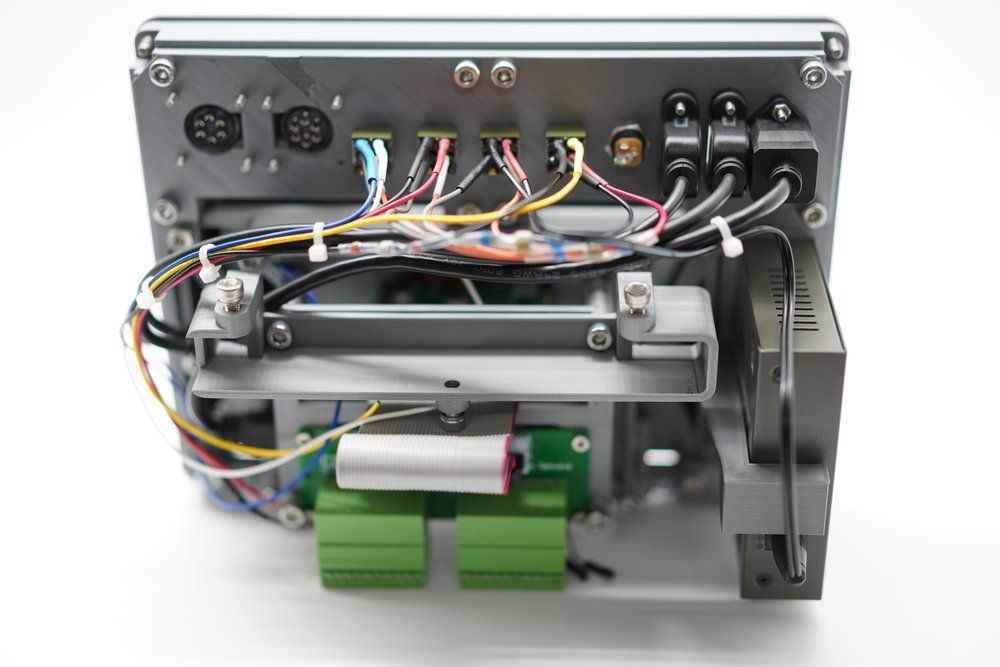
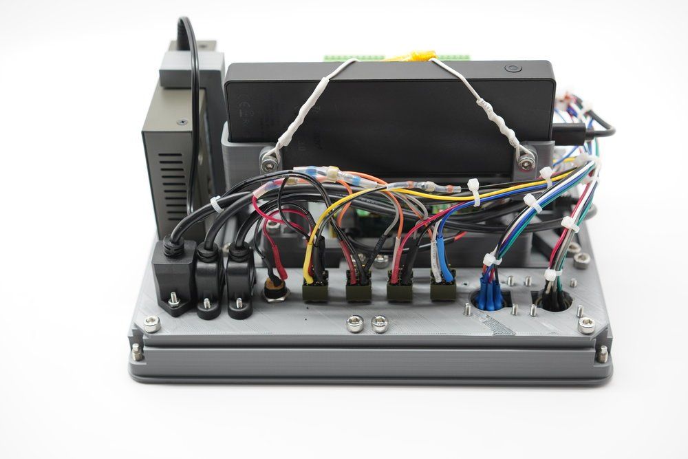
New Features
Finally, there are several cool features I added that I am really proud of. That includes a wire handle at the top to make it easy to pull from the enclosure. It’s also a considerable length of wire, so it can be used as spare wire in an emergency.
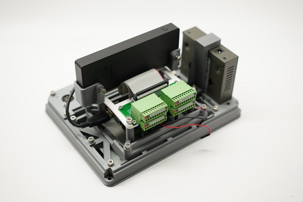
I also added an internal battery with a custom frame- this battery is giving me some trouble so I may replace it. I also did the same trick with the wire handle- it’s essentially a twisted wire with heat shrink to keep it from unraveling.
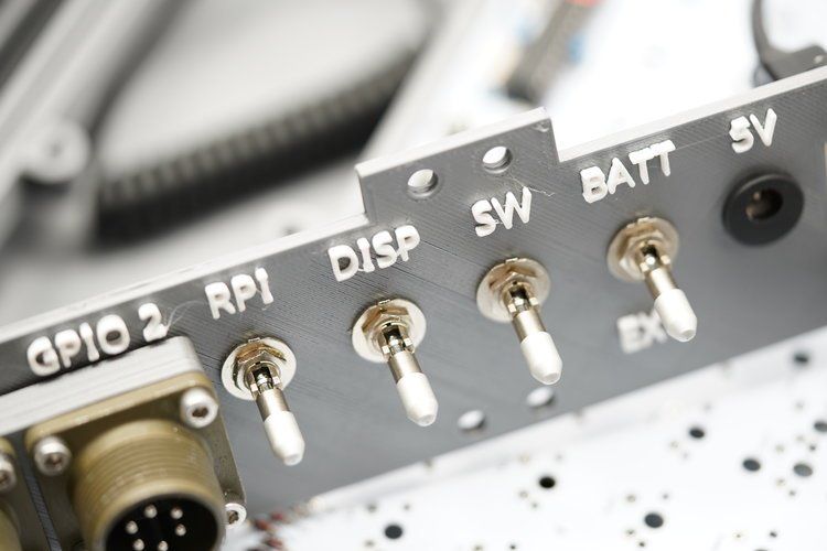
I added locking switches this time too, and my favorite new feature is the ability to turn all components on and off individually, and to switch power between the internal battery and an external one. I added the network switch too- no heavy mods here besides splicing the power adapter to re-use the barrel connector.
I also added cooling vents- the internal Pi 4 has a fan on it, but it needed vents too- so if you look close you can see vents above the connector panel and above the display.
Finally, with the best for last, a little trick that I used created an effect I love- the use of two colors on the printing of the panel. The panel is mostly grey, but the raised lettering is printed in white. I’m really happy with the result.
Next month I’ll be focused on my collaboration with Big Blue Saw to update my 3D printing capabilities, by using their waterjet services to build two new 3D printer enclosures out of aluminum. You can follow along on my Instagram and Twitter accounts while I document that build.
Beyond that, there are some cool plans I have for the Raspberry Pi Recovery Kit:
- Automate mirroring of Raspberry Pi images
- Create a repository for apt packages for Raspbian in case of an extended internet outage
- Script the periodic downloads of Linux install images
Thank you for reading! This was a fun project to work on, and I hope someone remixes it and comes up with their own. All the parts are listed below, and the 3D files are shared under the Creative Commons license for noncommercial use.
Parts List
- Pelican 1300 Case
- Raspberry Pi 4
- Raspberry Pi Fan
- Raspberry Pi 7” Touchscreen Display
- Raspberry Pi Terminal Block Adapter & Ribbon Cable
- Hookup Wire
- Space Grey PETG Filament
- Ethernet jack panel connector
- Barrel jack power connector
- USB panel connectors
- Plaid Ortholinear Keyboard Kit
- Cherry MX Silent Keyboard Switches
- DSA Beyond Keycaps
- NKK Switches or find them on eBay for much cheaper
- Mil Spec Connectors (panel and cable)
- Netgear Switch
- Stainless M5 Screws (Mostly 12mm)
- Stainless set screws
- Clevis Rod Ends
- 3D Files (Tinkercad and Thingiverse)
- (Added 4/19/2020) Sample wiring diagram on Github

Comments ()